Working Principle of the Pirani Gauge
The traditional Pirani vacuum gauge, originally invented in 1906 by Marcello Stefano Pirani¹, is based on a hot metal wire suspended in a tube that is exposed to gas pressure media. The Pirani gauge measures the vacuum pressure dependent thermal conductivity from the heated wire to the surrounding gas. The heated Pirani sensor filament is typically made of a thin (<25 µm) Tungsten, Nickel or Platium wire.
As gas molecules collide with the filament wire, heat is transported from the hot wire. The heat loss is a function of the gas pressure and at low pressure the low gas density and long mean free path between gas molecules provides a low thermal conductivity. At high pressure the high gas density and short mean free path between molecules will result in high thermal conductivity.
Marcello S. Pirani¹ already described in his first publication three modes of operation of the Pirani sensor, where either voltage, current, or temperature is kept constant. Later, pulsed operation was described in the literature and utilized in commercial products.
The Pirani sensor wire can be operated in different modes:
- Constant Voltage
- Constant Current
- Constant Temperature (resistance)
- Pulsed Operation
Fundamental for all types of Pirani operation is that the Pirani sensor wire filament must have a high temperature coefficient of resistance. A high temperature coefficient ensures that these changes in temperature or heat transfer from the wire are detectable through changes in resistance as function of pressure.

Constant Voltage Pirani operation mode
Marcello Pirani¹ described in 1906 the fixed voltage operation in original German language:
“Die Spannung, die an den Draht gelegt ist, wird konstant gehalten und man beobachtet bei verschiedenen Drucken seine Widerstandänderung bzw. die Änderung des ihn durchfließenden Stromes.“
or in English translation:
“The voltage applied to the wire is kept constant, and its change in resistance or the change in the current flowing through it is observed at different pressures.”
Constant voltage mode applies a fixed voltage to the sensing circuit, and the resistive change as a function of pressure is measured. In constant voltage mode, the power to the sensor filament is not adjusted, and the temperature of the sensor filament changes with pressure or gas density. Due to the thermal time constants in a traditional wire Pirani, this mode of operation is not practical for traditional metal wire Pirani gauges.
Additionally, constant voltage operation results in a temperature change of the sensor filament throughout the pressure range, which requires advanced techniques to compensate for variations in ambient temperature.
Constant Current Pirani operation mode
In constant current mode, a current source provides power to the sensor circuit, and the change of resistance as a function of pressure is measured to determine the vacuum gas pressure.
The constant current operation has similar tradeoffs as the constant voltage operation described above.
Constant Temperature Pirani operation mode
Marcello Pirani¹ also described the fixed temperature operation in his first publication of the Pirani invention as he wrote in original German language:
“Der Widerstand, also die Temperatur des Drahtes, wird konstant gehalten und man beobachtet die Energie, die dazu gehört, um diese Temperatur bei verschiedenen Verdünnungen zu erzielen.“
or in English translation:
“The resistance, i.e., the temperature of the wire, is kept constant, and the energy required to maintain this temperature at different levels of dilution is observed.”
In 1919 Masamichi So. ² progressed Piranis work and described his experimental study of the Resistance Vacuum gauge where he also concluded that the thermal conductivity of air is directly proportional to pressure fra 1E-5 to 2E-3 Torr.
The most common operation of the Pirani sensor or gauge is constant temperature, also referred to as constant resistance. In constant temperature mode, the Pirani sensor wire is kept at a target temperature, where the power is adjusted by a control loop as a function of the current through a reference resistor connected in series with the Pirani sensor wire. The control loop adjusts the sensor wire resistance to match the resistance value of the reference series resistor. The applied power to the sensor circuit is a function of pressure and is used to calculate the measured pressure.
The control loop can be maintained by an operational amplifier in a balanced Wheatstone bridge configuration or by a microcontroller unit that, through an analog-to-digital converter, actively regulates the power to the Pirani sensing circuit.
The constant temperature operation of the Pirani sensor is also referred to as constant resistance because the sensor wire resistance is kept at a target value, and thereby at a target temperature, by adjusting the power to the sensor wire.
In constant temperature mode, a fixed series resistor with the equivalent resistive value of the sensor wire at the target temperature is typically used as a reference to maintain the sensor wire temperature.
Pulsed Pirani operation
The pulse operation of a Pirani sensor was described by the German Professor W. Jitschin and S. Ludwig³ in 2004. The invention utilizes a fixed resistor in series with the Pirani sensor wire, where pulse power is applied to the sensor circuit. The pressure-dependent heat-up rate of the Pirani filament is measured over the series resistor to calculate the pressure. The pulse operation requires advanced calibration and temperature compensation techniques.
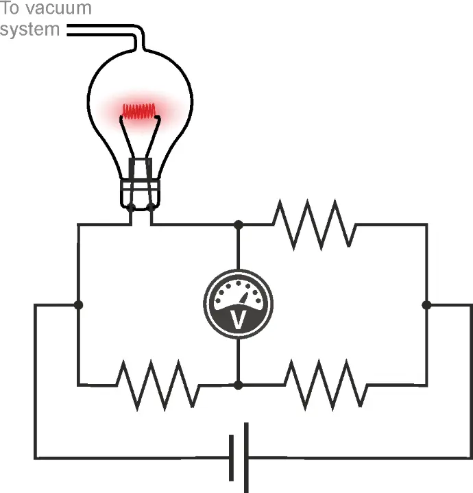
Pirani Wheatstone Bridge
Marcello S. Pirani¹ furthermore described in his first publication of the Pirani measuring principle that the heat-loss sensor could be operated in a Wheatstone bridge circuit.
The unbalanced Wheatstone bridge utilizes the constant voltage operating principle, while the balanced Wheatstone bridge utilizes the constant temperature operation.
When operating, the Pirani wire filament is typically used in a balanced Wheatstone bridge circuit, where one leg of the bridge is the Pirani filament, and the other three elements of the bridge circuit balance and temperature-compensate the circuit.
The Wheatstone bridge can be operated as a balanced bridge in constant temperature mode, where the power to the Pirani sensor element is loop-controlled by an operational amplifier or a microprocessor to maintain the Pirani sensor element at a constant target temperature.
H.R. Hinder and G. Suss⁴ describes in 1976 the difference between the balance and unbalanced bridge circuit and observes long time constants of several seconds that occur when the sensor wire in an unbalanced bridge needs to achieve new temperature when pressure changes.
Temperature Compensation
Under normal operation of a Pirani gauge, the ambient temperature will vary, and without temperature compensation, the Pirani gauge would not be able to provide usable pressure measurements. To apply accurate temperature compensation to the Pirani circuit, the ambient temperature must be measured. The temperature can be measured internally or externally to the vacuum chamber; however, to reduce temperature gradients, it is preferred to measure the temperature internally in the vacuum chamber, as close as possible to the Pirani sensor filament.
J. English, B. Fletcher, and W. Steckelmacher⁵ demonstrated techniques for temperature compensation of the wire Pirani gauge by using an auxiliary resistor to measure ambient temperature.
In traditional wire Pirani designs, measurement of temperature close to the sensor wire is not possible, but in modern MEMS Pirani sensor designs, the temperature-sensing resistor is embedded in the structure, enabling highly accurate temperature measurement less than a millimeter from the pressure-measuring heat-loss filament.
The advantages of utilizing temperature measurement close to the Pirani sensor filament for temperature compensation purposes within the vacuum chamber were described in 1998 by O. Wenzel and C. K. Bak.⁶
Evolution of the Pirani measurement technology – Pushing the boundaries
The Pirani gauge, traditionally using a heated wire to measure pressure by detecting heat loss to the surrounding gas, has evolved significantly with MEMS (micro-electro-mechanical-system) sensor technology. In the MEMS version, a resistive element is placed on an ultra-thin suspended diaphragm instead of a traditional wire filament. This innovation enhances performance due to several factors:
- Miniaturization: The small scale of MEMS allows for more precise measurements.
- Reproducibility: Semiconductor manufacturing processes ensure consistent production quality.
- Low Operating Temperature: Reduced heat loss improves stability and power efficiency.
- Improved Temperature Compensation: This helps achieve more accurate and reliable readings across a broader range of conditions.
The first MEMS-based Pirani gauges was commercially introduced in 1993 by Wenzel Electronics, a Danish technology startup founded by Ole Wenzel. The operation of the novel MEMS Pirani gauge invention was described by O.Wenzel and C.K.Bak ⁶ in 1998.
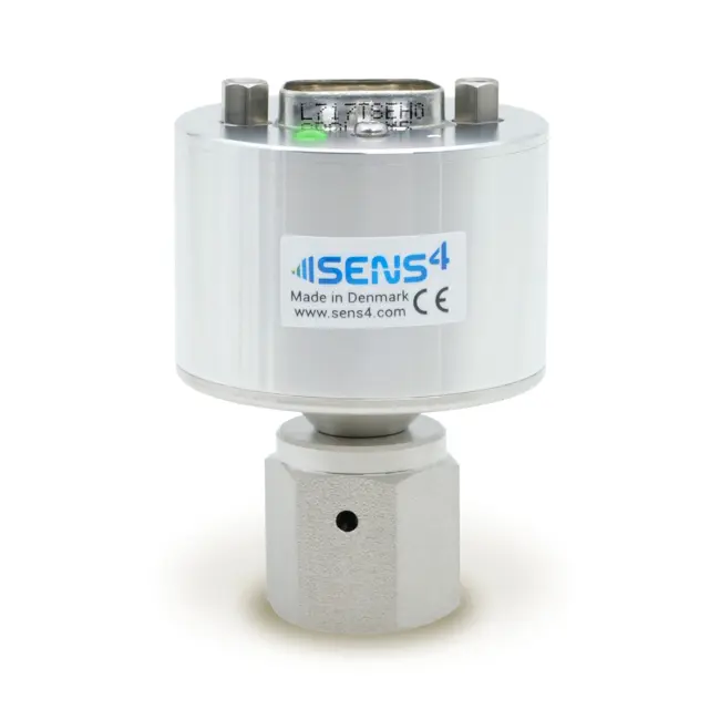
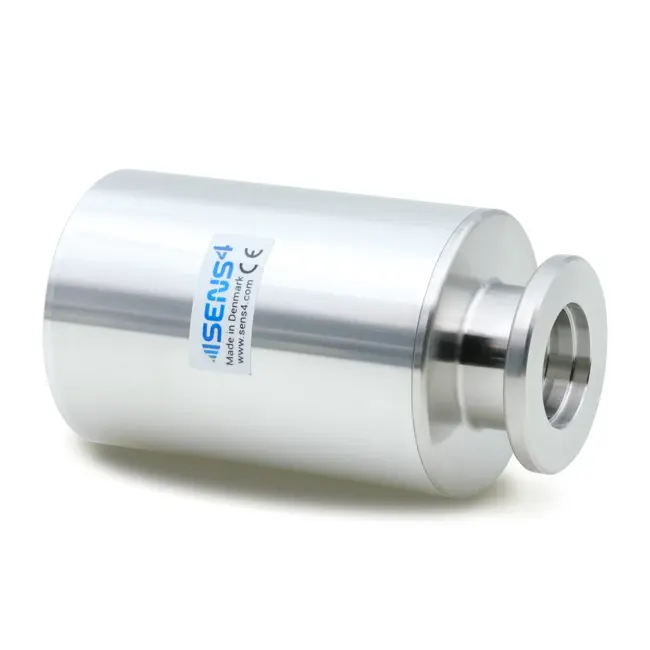
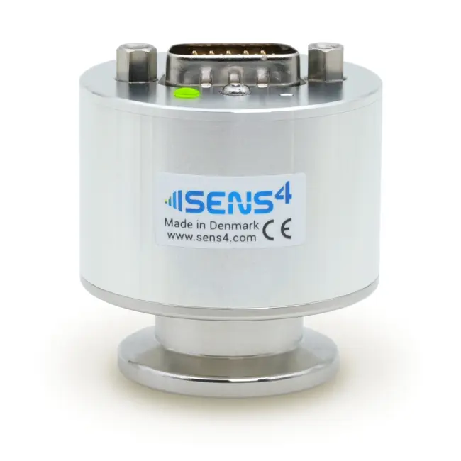
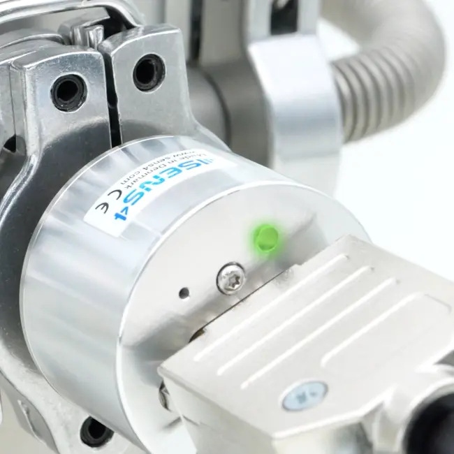
In 2019, Sens4 introduced the next-generation SmartPirani™ transducer ⁷, which pushed the boundaries of the Pirani technology by lowering pressure detection limit by an order of magnitude to 1.0E-6 mbar (7.5E-7 Torr).
The SmartPirani™ offers today industry-leading stability and precision, making it highly effective for applications requiring ultra-low-pressure measurements.
References
- Selbstzeigendes Vakuum - Messinstruments; Marcello S. Pirani, 1906, Deutsche Physikalische Gesellschaft, Verh.24(8): 686–694.
- The Resistance Vacuum Gauge by Masamichi So., April 3, 1919.
- Gepulstes Pirani-Vakuummeter: Berechnung von Aufheizung und Abkühlung by W. Jitschin und S. Ludwig, Vakuum in Forschung und Praxis 16 (2004) Nr. 6 page 297–301
- Pirani manometer with linearized response, H. R. Hidber and G. Suss, Institute of Physics. The University of Basel. Basel. Switzerland (Received 2 February 1976
- A wide range constant-resistance Pirani gauge with ambient temperature compensation, J English, B Fletcher and W Steckelmacher Journal of Scientific Instruments 1965, Volume 42, Number 2
- The MicroPirani: a solid-state vacuum gauge with wide range: O. Wenzel and C.K.Bak, Vakuum in Forschung und Praxis (1998) Nr. 4 page 298-301
- Record-breaking ultra-wide range SmartPirani ™ vacuum transducer unveiled: Sensor land: https://www.sensorland.com/PRPages/Sens4-001.html
